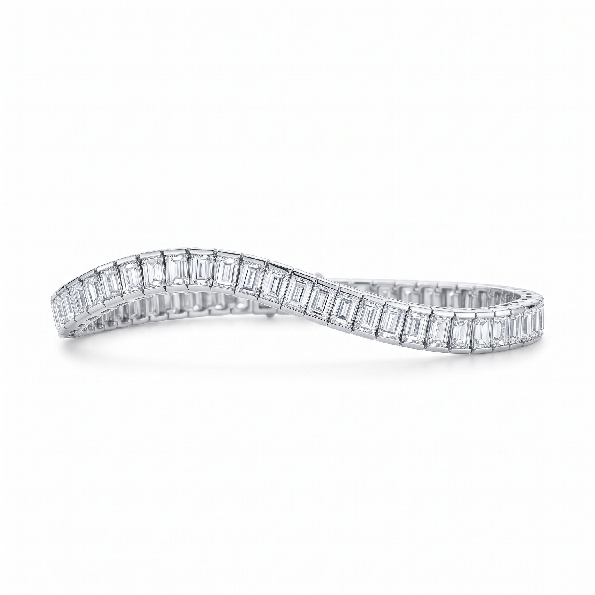
Outline & Topics Covered
- Planning the ring: finger size, metal, and gemstone
- Building the shank in Rhino or MatrixGold
- Designing the stone seat and prong placement
- Validating for casting: wall thickness and manifold check
- Exporting the final 3DM and STL files
The Digital Engagement Ring Workflow
Creating a custom engagement ring CAD design requires precision at every stage. From the initial client brief to the final castable STL file, each decision — finger size, prong height, girdle seat depth — directly impacts the quality of the finished piece. This guide walks through the complete professional workflow.
1. Planning: Finger Size, Metal, and Stone
Before opening your CAD software, define three parameters:
- Finger size — build the shank to the exact target size. Resizing after casting is possible but adds labor and risk of distortion in pave settings.
- Metal — 18K gold shrinks approximately 1.5% during casting; platinum shrinks 2.0%. Factor this into your shank wall thickness.
- Stone dimensions — measure the exact girdle diameter and depth of the center stone. Seats built 0.05mm too small will crack the stone during setting.
2. Building the Shank in Rhino or MatrixGold
In Rhinoceros 3D, build the shank by revolving a profile curve around the finger axis. Set the inner diameter to the target finger size (e.g., 17.35mm for a US size 7). The minimum wall thickness for the shank should be 0.8mm for gold and 0.9mm for platinum to prevent porosity during casting injection.
In MatrixGold, use the Shank Builder parametric tool — it automatically calculates inner circumference from ring size and lets you set taper, width, and profile shape with sliders instead of manual curve drafting.
3. Designing the Stone Seat and Prong Placement
The stone seat depth should match the girdle thickness of your diamond plus 0.05mm of extra clearance. Prongs should be designed with a minimum width of 0.5mm at the tip and an overlength of 0.3–0.4mm above the final finished height — this gives the stone-setter material to push over and bead without running short.
4. Validating for Casting
Before exporting, run a ShowEdges check in Rhino (Analyze > Edge Tools > Show Edges) to confirm no open edges exist. Join all surfaces into a single closed polysurface. The final model should display as a Closed Solid Polysurface in Rhino's properties panel.
5. Exporting 3DM and STL Files
Save the finalized model as a .3DM source file for your records. Export a separate STL file with maximum mesh density (0.005mm max distance, 0° angle tolerance) for your wax printer. Our library provides pre-validated, casting-ready 3DM and STL engagement ring files — like this multi-diamond halo engagement ring CAD file — so you can skip directly to manufacturing.